This project is for detecting human ECG (Electrocardiogram, or EKG). A tiny amplifier is embedded (<1mA). The on-chip Timer, ADC and DMA (double buffering) are used for getting ECG data. An IIR filter and hardware LCD scrolling are used for ECG rendering. User can simply touch the Primer by 2 hands, his/her ECG trace is scrolling alive on the LCD screen. The instant heart rate is displayed with beep sound and LED flashing. The device also delivers and displays the ECG on a PC through the USB cable.
PROJECT DESCRIPTION
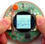
Figure 1 is the ECG Primer in operation. It is a STM32 Primer with two copper foils placed on each side of the front circle. These two metal foils are the ECG electrodes. User can place his/her both thumbs on the copper foil to start the operation. The ECG trace is scrolling on the LCD display. The heart rate calculated and display on the top of the LCD display while the LED and beep sound indicating the pulse detected.

Figure 1. ECG Primer in operation. Two metal foils are on each side of the ECG Primer for the ECG detection. The heart rate is shown on upper-left corner of the screen.
The ECG Primer consists of an extern ECG amplifier circuit for signal conditioning, the STM32 on-chip mixed signal processing peripherals for the data acquisition resources and the software handler for rending the ECG data and delivering ECG data to the USB port (Figure 2).

Figure 2. The ECG Primer block diagram
External ECG Amplifier Hardware
The external ECG amplifier circuit (less than 25 electronic components) is a tiny PCB embedded in the STM32 Primer enclosure (Figure 3. The sample of the PCB circuit was mailed to Raisonance, separately). Figure 4 is the ECG circuit schematic (it is also in the uploaded project zip file) and Figure 5 is the BOM for the PCB.
The first stage of the ECG amplifier circuit is an instrument amplifier (U1). It has high common mode reject ratio (CMRR) for eliminating the common mode noise, such as the 50 or 60 Hz AC interference. The gain is set to 5. Because human skin contacting the ECG electrode may create a small DC voltage offset, an integrator (U2D) is used for compensating this DC offset by feedback it to the reference pin of the instrument amplifier. The human ECG signal is very small (in 1 mV range).The gain of the second amplifier stage (U2A) is set to 200 and total gain of the circuit is about 1000 so that the ECG is in right voltage range for the analog to digital converter (ADC). The output of the ECG amplifier is connected the ADC input 2 (AIN2, pin 16 of STM32 Primer J1 connector). U3 is the switching power supply for generating +5V and -5V rails. The power and ground are also connected to the J1 connector. The instrument amplifier, operation amplifier and power regulator are lower power and the entire circuit current consumption is less than 1 mA.

Figure 3. The tiny ECG Amplifier PCB is embedded at back of the STM32 Primer main board. The input of ECG Amplifier is connected to font electrodes while the output and power supply are connect to the J1 connector.
.jpg)
Figure 4. The ECG circuit schematic

Figure 5. Bill of Material for the ECG PCB
ECG Data Acquisition
The ECG signal is digitized by ADC1 (channel 2, AIN2). The sampling rate is 480/sec. ADC1 is set to the single conversion mode with the external event triggering the conversion. The conversion trigger source is the Timer1 (TIM1) channel 1. The prescaler of TIM1 is set to 24 while the modular register (Auto-reload register TIM1_ARR) is set to 6250. The system clock frequency is 72MHz and the TIM1 channel output is 72MHz / 24 / 6250 = 480 Hz. DMA channel 1 is setup for transfer the ADC sampled data from the ADC regular data register (ADC_DR) to a memory buffer. The memory buffer size is 240 bytes to hold 120 16-bit data entries, which is size for a period of ¼ second. The DMA Half-Transfer-Interrupt (HTIE), Transfer-Complete-Interrupt (TCIE) and destination memory address auto-increment mode are enabled. The DMA channel 1 destination address is increased each time a sampled data is transferred to the memory buffer until it reaches to the end of the buffer. Then the DMA is automatically wraps the destination address back to the beginning of the memory buffer to form a circular buffer scheme. The double buffering (or so called Ping-Pong buffering) is made by the dual interruptions. When the memory buffer is filled with half of the buffer size data, the Half-Transfer-Interrupt flag (HTIF) is set and signal an interruption. The interrupt service routine (ISR) is activated and a global pointer (for ECG data rendering) is set to point the beginning of the memory buffer. The data in first half of the memory buffer (60 data entries), therefore, is being processed by the ECG data rendering procedure (in the Application_Handler function) while the DMA continue transferring the ADC sampled data to the second half of the memory buffer. When the memory buffer is full, the Transfer- Complete-Interrupt flag (TCIF) is set and there ISR is activated again. At this time, the global pointer is pointing to middle of the memory buffer. So the ECG data rendering procedure processes the data in second half of the memory buffer while the DMA continues transferring the DAC sampled data to first half of the memory buffer (see Figure 2). In this way, the data acquisition and data rendering is decoupled without pending each other. The chunk of the buffered data (representing the period of 1/8 second) is served at 8 Hz.
ECG Data Rendering
The ECG render procedure is in the Application_Handler function. While the Application_Handler function is activated at 30Hz (when sysclk = 72MHz), the ADC data buffer for process is at a rate of 8 Hz. The global pointer (pointing to the memory buffer) is evaluated each time the Application_Handler function is called. If the global pointer is not null (a block data is ready), the ECG data rendering procedure starts. The data is first processed by a 4th order Chebyshev IIR (Infinite Impulse Response) low pass digital filter (LPF). The LPF cut-off frequency is set to 40 Hz to remove the higher frequency noise (including the 60 Hz AC interference at USA and 50 Hz AC interference at Europe). In order to speed the filtering process and reduce the code size, the fixed point process instead of floating point process is used in the filtering. All the coefficients are pre-scaled by 65536. Only integer multiplications are involved during the calculation. The final result is then shifted 16-bit right (equivalent divided by 65536). The filter procedure also reduces the data rate by 4 times for easy rendering at the low resolution LCD display. The filtered data (reduced to 15 bytes) is then rendered at the LCD display. In order to increase the ECG trace drawing efficiency and avoid the display flickering, the LCD hardware scroll function is used. First, the entire LCD drawing is shift to left 15 pixels by the LCD scrolling commands (the SCRLAR and VSCSAD commands). Then the 15 pixels wide area at right most of the screen is erased. The new trace is drawn on the erased area. In this way, the ECG trance is continuously scrolling from right to left on the screen at the 8 Hz update rate without the screen flickering.
In order to calculate the heart rate, a threshold based QRS wave detector is used. The threshold is also drawn at the screen for visual assessment. If the signal is over the threshold, a short beep is on and the red LED flashes to indicate the heart pulse. The interval between the detected QRS waves is converted to heart rate and displayed on the up-left corner of the LCD display. A hysteresis at the threshold and an inhibiting period are used to avoid the mistake triggering by the noise or high T-wave.
USB Data Transfer
Besides drawing the ECG trace on the LCD display screen, the device also sends the ECG data to a PC through the USB port (the USB port behind the pushbutton). The USB data transfer is using the Human Interface Device (HID) class. The code implementation references the PrimerMouse project posted on the stm32circle.com website. The HID report descriptor is rewritten. Instead of the predefined mouse and pointer device, the report descriptor usage page and the usage are vendor defined classes. The input report size set to 16 for the16-bit ECG data and the report count is set to 60 for sending the entire block of the ECG data at once. Other descriptors are also modified accordingly. When the block of ECG data is ready, besides the trace rendering the Application_Handler function also copies the ECG data to the 512-byte USB dedicated SRAM memory for the input report at Endpoint 1. Because the data block is ready every 128 ms (in 8 Hz), the interrupt (polling) interval is set to 64 ms for guaranteeing there is no missing for the input report. When the device senses the report request, if the data is ready the device sends the data to the host PC.
PC USB Handler and ECG Display Software
The PC USB handler and ECG display program is written in Windows .NET environment using the C# language. Figure 6 is screenshot of the PC host GUI. Since the PC software development is not in the scope of the contest, detail description is omitted. However, the PC software executable is provided in the uploaded zip file (require .NET framework 2.0 or later installed).

Figure 6. ECG trace displayed on the PC screen.